If you’ve ever had a part that “technically” met spec but still didn’t fit—or worse, caused an assembly to jam or rattle—you’ve felt the consequences of poor tolerance planning.
Tolerance analysis isn’t flashy, but it’s one of those things that separates a good design from a bad one. At Ziqual, we’ve seen hundreds of parts come through from customers. The ones that go smoothly aren’t always the simplest—they’re the ones where someone took the time to think through how things would actually go together.
This article is about doing that.
What Is Tolerance Analysis, Really?
At its core, tolerance analysis is about understanding how variations stack up.
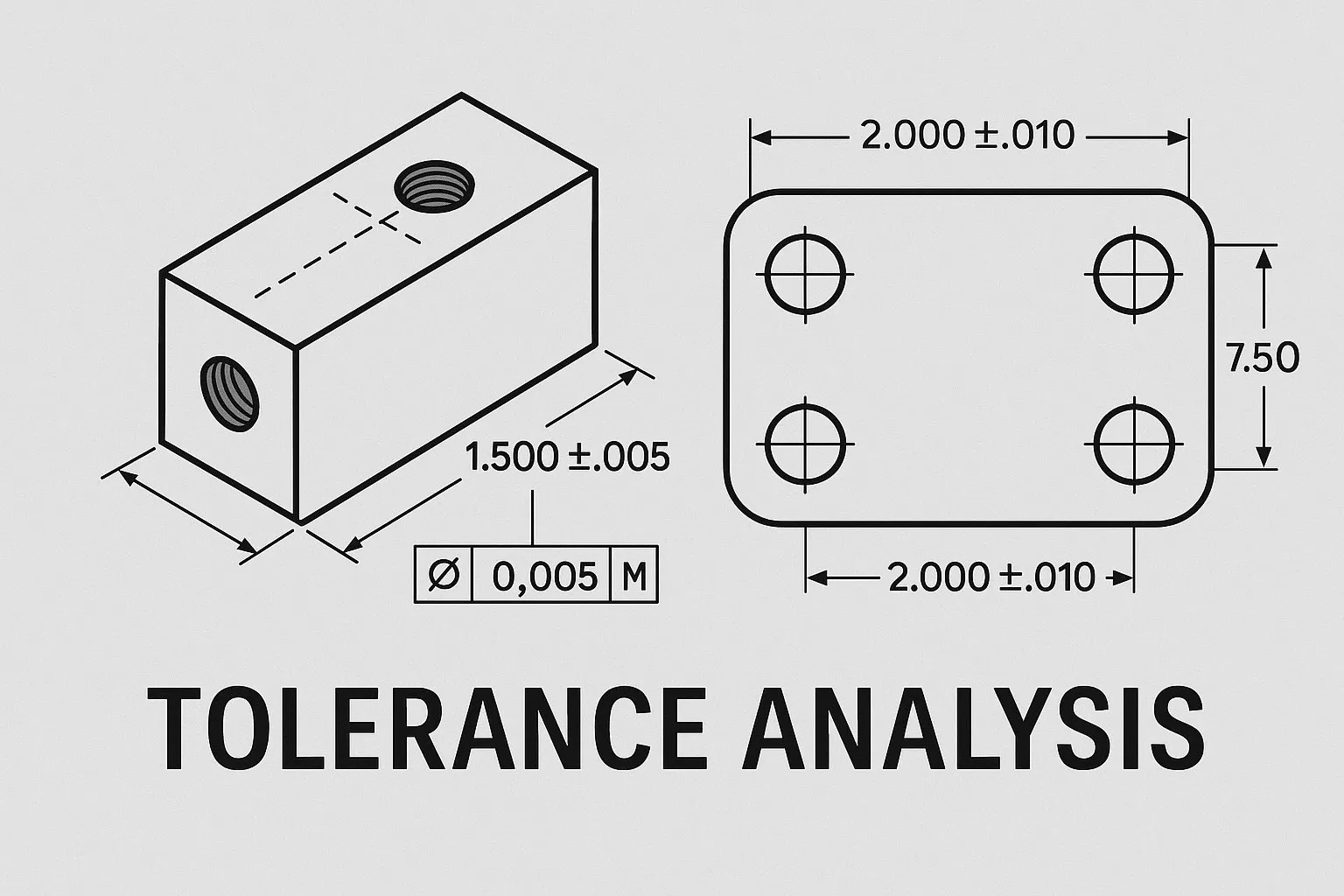
No part is ever made perfectly. There’s always some deviation. Tolerance analysis is the process of figuring out how much deviation you can allow in each part without causing problems in the assembly.
The goal is simple:
👉 Make sure that when all the imperfect parts come together, the final product still works as intended.
Why It’s Worth Doing
It’s easy to wave off tolerancing until there’s a problem. But here’s what’s at stake:
- Fit: Will parts assemble without interference or gaps?
- Function: Will moving components bind, jam, or misalign?
- Cost: Are you over-tolerancing and driving up machining or inspection costs?
- Risk: What happens if two parts on opposite ends of spec meet?
A little tolerance planning up front saves a lot of headache downstream—especially if you're sending parts out to be machined or manufactured by someone else.
Common Types of Tolerance Stackups
There are a few ways to approach stackups. The method depends on the complexity of your assembly and how critical the tolerances are.
1. Worst-Case Stackup (Conservative)
Assumes all parts are at their max or min tolerance simultaneously. Safe, but often overkill.
Use it when:
- Failure isn’t an option (e.g., safety-critical assemblies)
- You’re working with low volumes and can afford tighter tolerances
2. Statistical Stackup (More Realistic)
Assumes dimensions vary in a bell-curve (normal distribution). Tighter where needed, looser where not.
Use it when:
- You’re producing at scale
- You can tolerate some controlled risk
- You’re trying to avoid unnecessarily tight tolerances
3. Monte Carlo Simulation (Data-Driven)
Simulates thousands of builds based on actual variation data. Powerful, but needs a lot of input.
Use it when:
- You have solid manufacturing data
- You’re optimizing a complex, multi-part system
Key Things to Watch For
• Over-tolerancing
Designers often play it safe and spec ±0.001” everywhere. That might work on CAD, but in reality? It’s expensive, slow to inspect, and often unnecessary.
Tip: Only tighten tolerances where they affect function or fit. Otherwise, give your machinist some breathing room.
• Missed Stack Paths
Sometimes tolerances don’t cause trouble on a single part—but they do when stacked across several. Think about:
- Hole locations across multiple plates
- Axial clearances in bearing assemblies
- Cumulative gaps in enclosures
If you ignore the full path, the final fit might surprise you.
• Mismatched Tolerances Across Suppliers
One shop might hold ±0.005” all day. Another might quote ±0.001” but not hit it. If your parts are sourced from multiple vendors, tolerance mismatches become a real issue.
How to Approach It (Without Going Crazy)
You don’t need to run full simulations on every design, but here’s a practical workflow:
- Identify Critical Features
- Where does the part interface with others?
- What tolerances affect alignment, fit, or motion?
- Do a Simple Stackup Check
- Add up dimensional variations along the path
- Start with worst-case if unsure
- Ask: What Happens at the Limits?
- What if one part is tight and the next is loose?
- Will it still assemble and function?
- Adjust Tolerances Accordingly
- Loosen where it doesn’t matter
- Tighten where it does
- Get Input From Your Manufacturer
- Machinists can often tell you what’s easy to hold and what’s going to cost you
A Real-World Example
Let’s say you’re designing a housing with a shaft that runs through two bearings. You’ve modeled it in CAD with perfect alignment, perfect fit.
Now you send out the parts. One hole is off by +0.003", the other by -0.002", and your shaft is ground to the low end of its spec.
The result? The shaft binds. Everything “meets spec,” but the stackup was never analyzed. You end up hand-filing holes or scrapping the batch.
We’ve seen it happen more than once.
Final Thoughts
Tolerance analysis doesn’t have to be complex, but it does have to be done.
You don’t need an advanced simulation every time. You just need to think critically about how parts will actually go together in the real world—under real manufacturing conditions.
If you’re ever unsure, ask. A good machinist, engineer, or supplier will usually spot a tolerance problem before it turns into a production problem.
At Ziqual, we help customers figure this stuff out early—before money gets spent, and before parts go to scrap. If you’ve got an assembly that makes you nervous, send it over. We’ll take a look.