If you've ever sent a part out for machining and received something that looked right but didn’t fit right, you’ve already met the problem that GD&T solves.
Geometric Dimensioning and Tolerancing (GD&T) is the universal language engineers use to describe exactly how a part should be made—not just the size, but how it should behave in the real world. At Ziqual, we work with shop floors every day, and GD&T is one of the biggest predictors of whether a project goes smoothly or becomes a back-and-forth guessing game.
Below is your no-nonsense crash course—what each symbol means, when to use them, and how they can save you money, time, and headaches.
Why GD&T Exists
Traditional dimensions tell you what geometry should look like on paper.
GD&T tells you how that geometry should function in real life.
It eliminates:
- ambiguity between designers and machinists
- interpretation errors (“Do they mean center it? Align it?”)
- unnecessary tight tolerances that drive up cost
And it guarantees:
- interchangeability
- consistent fits
- predictable assembly performance
Think of GD&T as engineering insurance—cheap protection against expensive failures later.
The Building Blocks of GD&T
1. Datums (Your Reference Frame)
Everything starts with datums—your ABCs.
They define the “zero points” of the part: a plane, a center axis, or a feature the rest of the geometry relies on.
A good datum scheme:
- creates stability
- reflects how the part will be assembled
- simplifies inspection
Bad datum choices are one of the fastest ways to confuse a machinist.
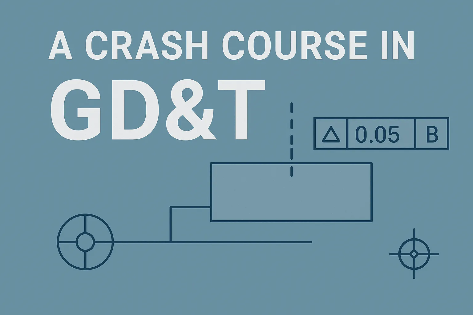
2. Feature Control Frame (The Instruction Box)
Every GD&T requirement is written in a little rectangular box called a feature control frame.
It tells the machinist:
- What tolerance type you’re using (like position or flatness)
- How big the tolerance is
- What datums the feature relates to
It’s the recipe card for making your part behave correctly.
3. Common GD&T Symbols (What They Actually Mean)
Let’s keep this practical. Here are the ones you’ll use 90% of the time:
Flatness
Controls how flat a surface must be.
Used when you need good contact—mounting plates, sealing surfaces, etc.
Parallelism
Ensures two surfaces are the same orientation but not necessarily touching.
Think sliding mechanisms or rails.
Perpendicularity
Controls angular squareness relative to a datum.
Critical for assemblies with tight alignments.
Circularity & Cylindricity
These control roundness.
Used for rotating parts, shafts, pins, holes, bearings.
Position (the most powerful tool in GD&T)
Tells you exactly where a feature—like a hole—should be relative to datums.
It also allows for tolerance zones, which often lets you loosen tolerances without hurting function.
Runout & Total Runout
Used for rotating parts like pulleys, shafts, and optical mounts.
It ensures the surface doesn’t wobble or wander during rotation.
When Should You Use GD&T?
Use it when:
- A part must mate with another part
- A feature’s orientation matters
- A hole must be centered precisely
- A component rotates
- You want wider tolerances without sacrificing function
- You want machinists to stop guessing
Avoid using it like decorative stickers. GD&T should reflect functional intent, not make drawings look technical.
The Most Common Mistake
Over-tightening tolerances.
Designers often assume “tighter = better,” but that’s rarely true.
Machining cost rises exponentially when tolerances shrink—especially below:
- ±0.001"
- 0.005" position
- 0.001" flatness/parallelism
Before calling out a tight tolerance, always ask:
“Does the part actually need this to function?”
Most of the time, the answer is no.
Why GD&T Matters for Ziqual Customers
Clear GD&T means:
- shops quote faster
- shops machine more accurately
- fewer parts get rejected
- fewer reorders
- fewer delays
- less money wasted
And your design intent remains exactly how you imagined it—not translated, misinterpreted, or simplified on the shop floor.
At Ziqual, we see hundreds of drawings across industries every month. The best-performing teams aren’t the ones with the fanciest CAD models—they’re the ones who communicate tolerances cleanly and intentionally.
If You're New — Start Simple
You don’t need to master the full ASME Y14.5 standard.
Start with:
- datums
- position
- perpendicularity
- flatness
- parallelism
Use them only where they matter, and your drawings will instantly become more professional and much easier to machine.
Need Help Adding GD&T to Your Next Project?
If you have a drawing that needs a quick tolerance review—or you’re not sure whether a callout is necessary—Ziqual can help.
Upload your CAD and drawing on Ziqual.com, and we’ll help you design for both precision and manufacturability.